| Hardware | Control | Sim | State Estimation | Planning | EE | Data / AI | |
|---|---|---|---|---|---|---|---|
 |
Optimal Control, Robust Control | ROS + Gazebo | EKF | Embedded Systems | |||
 |
MuJoCo | Reinforcement Learning, Transformers | |||||
 |
Manufacturing, Design | Optimal Control, SysID | Luenberger Observers | I2C, CAN, BLDC Motor Drivers | |||
 |
Whole Body Control, Teleop | Isaac Gym | Cloud Computing (AWS) | ||||
 |
Optimal Control | Webots, ROS + Gazebo | EKF | A*, SLAM | |||
 |
Manufacturing, Design | Teleop | ROS + Gazebo | ||||
 |
Predictive Maintenance | Sensor Data Collection | Data Analytics | ||||
 |
Manufacturing, Gearboxes, Design | BLDC Motor Drivers | |||||
 |
Computer Vision | Data Analytics | |||||
 |
Manufacturing, Design | A* |
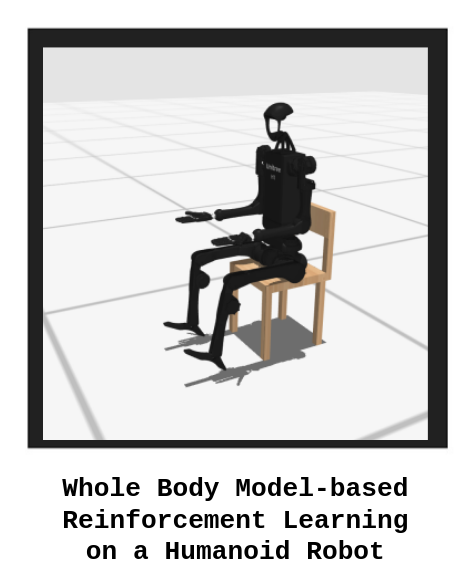
Model-based Reinforcement Learning and Transformer Architecture in a Humanoid Robot Environment
For decades, humanoid robots have been developed using model-based optimal controllers for whole-body locomanipulation tasks. However, generalizability to different tasks in uncertain or chaotic environments have been an obstacle for real-time deployment. By using parallelization in simulation, reinforcement learning seeks to not only decrease development time but also generalize the experiences of simulated robot agents across different environemnts and tasks. Through this group project, I was curious as to how reinforcement learning could be used to plan long horizon tasks and if there were any changes to make this learning problem easier.
The team used TD-MPC2, a model-based reinforcement learning paradigm, as an ideal candidate to control a multi-DOF humanoid robot. TD-MPC2 is evaluated on 104 control tasks across 4 different simulation worlds with a diversity of physics engines and robot agents. Relevant state information is exclusively encoded, with temporal difference learning incentivizing long-horizon control tasks. One set of pre-configured hyperparameters and a freely available dataset on HuggingFace allowed the group to prototype this solution for more immediate results.
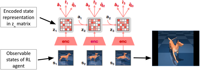 TD-MPC2 outline diagram. In this example, a musculoskeletal canine is simulated and controlled; due to the complex coupling and control outputs, this task would have been complicated at best for model-based methods.
To improve on this structure, the team used a decision transformer instead of the MLP used in the sampling for the TD-MPC2 model; in this new structure, a transformer architecture takes in the sequence of past actions, past states, and rewards while the output returns likely ations for the agent. A number of features makes this method attractive, such as the attention mechanism recording past actions and states to inform future actions and conditioning the transformer to return likely actions that incentivizes an ideal reward. This would change the structure of our reinforcement learning architecture to a sequence modeling problem, but this was amended by fixing the returns for the first return, similar to horizion-based approaches.
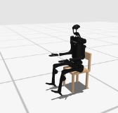
This structure was implemented on a Unitree H1 model in MuJoCo using the HumanoidBench testing environment. A hierarchical model for controlling low-level manipulation and high-level planning / control tasks was employed, with TD-MPC2 as the high-level planner. We trained the agent for 1 million training steps to sit in a chair, which is a complex task due to the contact dynamics and proprioception involved for a typical optimal control struture. To reduce training time, the hands were fixed to reduce the DOFs on the model and, thus, reduce the action space of the agent.
 |
 |
 |
A comparison between the goal (left), the baseline (center), and the improved (right) implementations.
The results of this experiment are promising: a trained transformer model was able to have a reduction in training time by 25% for relatively the same level of rewards for the sitting task. Also, the movements that the transformer-based architecture creates are much smoother, which can reduce the wear in joints on hardware and lead to motions that display better filtered results via local PD controllers.
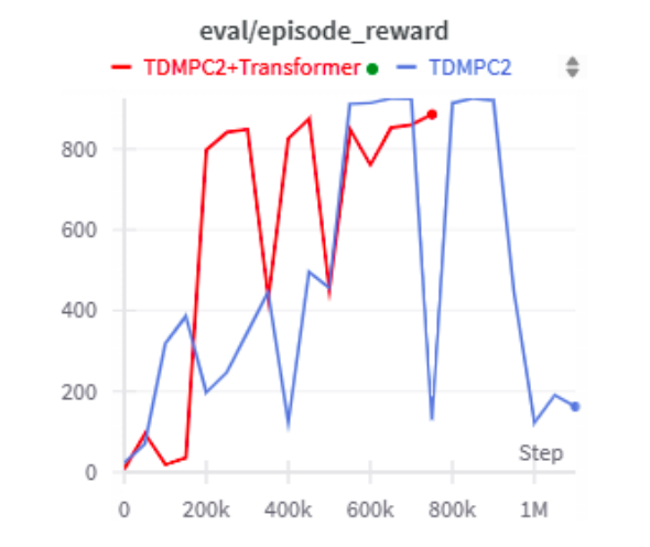 Results graph showing a reduction in >25% reduction in training time for model training.
Even though this work was done in a class project, I felt confident enough to showcase this experience as a technical presentation in a different class, which can be found here: 7-minute Technical Presentation
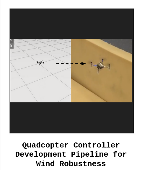
Quadrotor Controller Development Pipeline in Simulation and Hardware for Wind Robustness Testing
Drones fly through the air, which create a number of problems when trying to get a stable system. While these systems go to goal locations without crashing, their movement into different areas can cause or be affected by wind that destabilizes the system. This stability is critical for a number of purposes, such as surveying land inaccessible to ground-based robots, delivering payloads, and providing disaster relief to aid search-and-rescue operations.
This project works on a sim2real pipeline, in which controllers are derived in a high-level language such as Matlab or Python, simulated in ROS2 and Gazebo in C++ with wind conditions, and run in C on a Crazyflie 2.1 quadcopter with an STM32 microcontroller. This pipeline was so refined that, towards the end of the project, a controller was derived, simulated, and tuned on hardware in the span of two weeks!
For this project, I focused on two goals: setting up the ROS2 simulation with wind testing and the LQR derivation. I chose Gazebo as the simulation environemnt to program the drone controllers in C++ and add a 3D wind force effect based on the meshes of the drone. By testing the drone in simulation, preliminary tuning values can be found that roughly translated to hardware. Also, simulating the drone minimized hardware damage and, since the drone experienced fairly limited downwash / vorticies or other aerodynamic effects besides wind due to the focus on stabilization, the physics surrounding the drone could be effectively modelled.
 Wind robustness testing baseline for simulation, with teleoperated commands sent via the basic ROS2 keyboard teleoperation commands
I also implemented an infinite horizon LQR controller on the quadcopter in simulation and tuned on hardware with full state feedback (x y z, roll, pitch, yaw, dx, dy, dz, droll, dpitch, dyaw). Each control action was either the overall body force on the drone or the torques along the x, y, and z axes. To lower the computational restraints, I computed the LQR gains offline and tuned them iteratively on hardware. Something interesting to note: the final gains for the hardware followed a coupling format (one computed torque was tied to several states closely), which was similar to the cascaded PID structure implemented on another controller.
 LQR controller in C++ in ROS2 Gazebo simulation. The goal state was 1 meter above the ground plane and was not tuned to test baseline functionality in this demo.
Overall, 3 controllers developed: a Sliding Mode Controller, a cascaded PID controller, and a LQR controller. Evaluations on the performane of the controllers was done by tracking a square shape with a robustness test of 1m/s standing wind gusts. Overall, the Sliding Mode controller had issues with chattering between the different manifolds, but the LQR controller had the best overall wind stability with adequate position accuracy (<0.5 normalized orientation error, <2 normalized position error). The PID controller, which spent the longest in tuning on hardware, achieved similar results to the LQR controller.
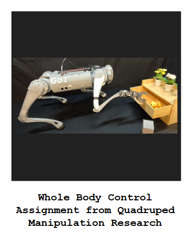
Graduate-level Course Assignment Creation: Quadruped Loco-Manipulation with Whole Body Control
Quadruped robots with four legs can go places where other robots cannot: over large obstacles, across gaps, and through tight spaces. Even though these quadruped robots have admirable athleticism, manipulating objects in the real world can be a challenge, especially if the objects are also in confined spaces. A solution to the problem of manipulating objects can be found in the paper “LocoMan: Advancing Versatile Quadrupedal Dexterity with Lightweight Loco-Manipulators”, which uses small arms on the calves of front legs of the robot to grab objects and interact with the surroundings. This research project is being adapted into a graduate-level course assignment as a part of ongoing work with Dr. Ding Zhao in his Modern Control Theory course and features an AWS-based quadruped control assignment in the Isaac Gym simulation environment.
Controlling the quadruped robot depends on what type of user command the robot should accept; the robot can support teleoperation mode, a bipedal standup maneuver on the hind legs of the robot, and manipulation mode using the 3-degree-of-freedom end effectors on the front legs. These different modes are changed through a finite state machine, which changes the way the controller on the robot prioritizes certain control objectives. The central control objectives are passed through a whole-body controller that takes in the state of the robot as well as desired states of the feet, torso, and end effectors. This data is processed by the controller that finds the optimal torque the motors should move to make the robot execute the action. Motor inputs are filtered through a PD controller that dampens the input torques and accounts for velocity and acceleration mismatch between the controller speed and real-life conditions. Once these torques are used, a state estimation technique is used to estimate the position and velocity of the robot and this information is fed back into the controller.
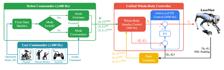 Block diagram for LocoMan paper, with finite state machine (Robot Commander, Green) and control architecture (Unified Whole-Body Controller, Red)
By using this system of mode commander and whole body controller, the LocoMan hardware and software implementation were able to manipulate small objects in narrow gaps through teleoperation as well as achieve numerous challenging tasks such as opening drawers. Work on the assignment for the course adaptation has focused on running the simulation in AWS and visualizing the robot in the Isaac Gym environment.
Want to follow along with the extra credit homework assignment I made? Here’s the assignment with AWS setup tutorial, mathematical derivation for the whole body control problem, and null space projection: Link to Assignment
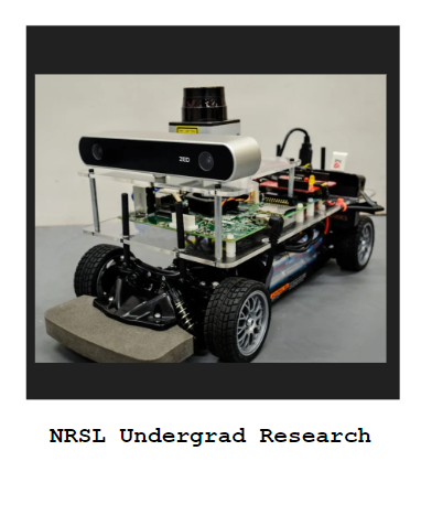
Networked Robotic Systems Lab at Penn State University
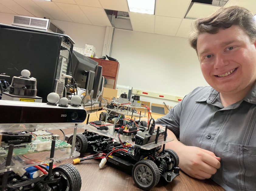
During my undergraduate experience at Penn State University, I became the lead undergraduate researcher for the Networked Robotic Systems Lab (NRSL). The project that I spent most of my time with used A* and path planning algorithms in MATLAB to navigate an unfamiliar area. This robot, which I helped prototype for lab demonstration, would connect to a Vicon motion capture system to record its position and determine possible trajectories.
The lab became unused during the pandemic, so my day-to-day duties also included developing a fleet of mobile robots that can be used in a variety of situations. These robots could be programmed via Arduino to run control or path planning algorithms in a graduate student lab setting or be upgraded with Jetson boards for research use.
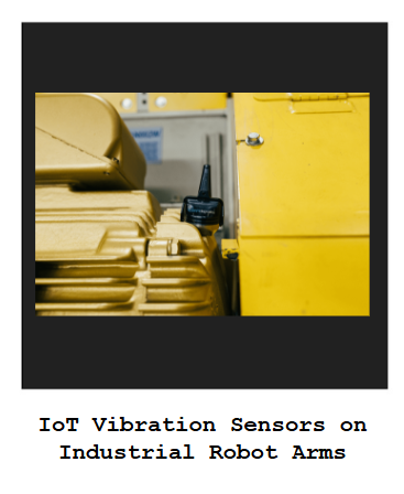
Predictive Maintenance of Industrial Robots using IoT Vibration Sensors
Industrial equipment with moving parts such as pumps and fans break down and have to be repaired, costing a company time and money while the production of goods halts. To avoid stopping production, predictive maintenance algorithms can be used alongside sensors or robots that proactively monitor machines for signs of imminent damage rather than reacting to equipment failures. This project, which was completed during an undergraduate internship at KCF Technologies, seeks to use industrial IoT vibration sensors placed on industrial arm robots to optimize sensor collection windows in an automotive use case.
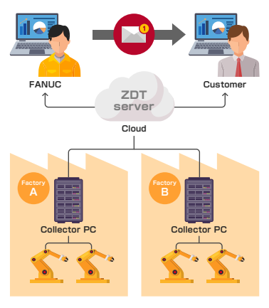
Industrial robots have several joints, all of which can fail from excessive wear on gearboxes. These failures can be predicted early by seeing the vibration on the joints for signs of excess forces and acceleration plots that spike in particular ways for gear wear. By measuring these vibration readings using a wireless accelerometer and processing data off-site as a service, industrial customers can maximize their time producing cars and prevent massive damage to their robots. These robots only show signs of failure when their joints are in motion, and the IoT sensor company providing the internship had an open problem to time sensor collection windows to robot motion. Some of these robots were of the Fanuc brand, which uses a software tool called Zero Down Time (ZDT) to store the output of programmed robots that shows the simplified motion commands called G-code. By reading this G-code, sensor collection windows can be selected that more precisely times the sensor readings to when the joints are under stress. This innovative way of synchronizing two forms of data not only preserved the privacy of the actual code used in production lines by only observing the output, but the arrangement also allowed for much flexibility in production lines by configuring the collection windows independent of any particular tasks, which can change dramatically as production lines are updated with new products.
The project was presented to peers and key decision makers at the internship company, which unfortunately experienced layoffs of almost all of the robotics-adjacent staff. The project was certainly innovative, and the ZDT portal for the robots later integrated a predictive maintenance feature mirroring that described in the presentation.
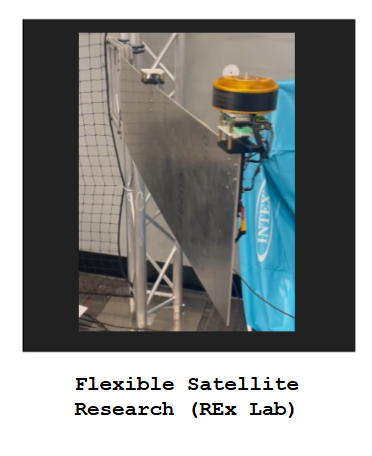
Flexible Satellite Hardware Control using a Distributed Actuation Approach
As satellite missions become more complex and expensive, the trend towards higher mass and volume payloads has to be balanced with hardware and control robustness in order to ensure mission success. With larger mass and volume payloads, flexible structures that make deploying satellites become more common but can induce unwanted vibration properties that complicate fine-pointing maneuvers such as stargazing or finding relative position near planets.
This research project explores how a distributed reaction wheel placement strategy can be beneficial for controlling the vibration of flexible structures in comparison to the standard centralized approach that is common throughout standard satellite designs. To demonstrate how vibration suppression techniques can work in this context, a hardware testbed has been developed that features a flexible cantilever beam with a single reaction wheel that controls the vibration of the structure at the dominant vibration modes of the structure.
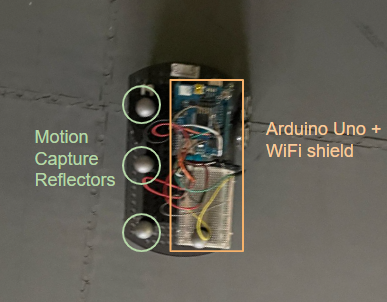
To demonstrate the potential effectiveness of the distributed vibration suppression system, an Aluminum 6061 beam is attached in a cantilever fashion and actuated with a brushless DC reaction wheel with inertial measurement unit sensors at the point of actuation. By activating this reaction wheel at certain frequencies, the structure can be vibrated in a fashion that suppresses extraneous movement. This vibration data, measured by the inertial measurement unit sensors, is transferred to a computer to enable real-time control and facilitate data collection.
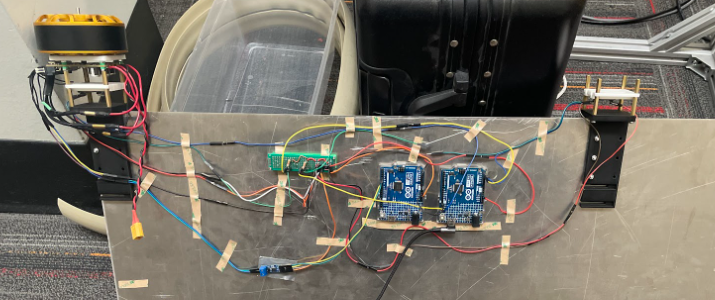 Internal electronics for the Flexible Satellite hardware testbed. On the side of the flexible structure, two microcontrollers (pictured in blue) facilitate data transfer from the computer to the reaction wheel (left).
This data collection setup can be used to create a state-space model essential for complex control algorithms via system identification. This system identification technique uses experimental data from the structure that was subjected to a range of frequencies from the reaction wheel; this data is run through the N4SID algorithm to provide a better estimation than a dynamics-based approach of the system because the experiments account for model mismatches and hardware inaccuracies.
 Flexible satellite hardware testbed undergoing system identification experimentation. A signal is sent to the motor that actuates the structure over a range of frequencies that cover the expected frequency of the controller and vibration frequencies of the structure.
Preliminary results of the hardware setup show promising results that could be of assistance to future research. To compare future results, a PID controller was developed that stabilizes the system over a period of about 15 seconds from a deflection of 10 centimeters. An improvement to PID control would be LQR, which would use the system identification results to control a more accurate model to suppress vibrations. These experiments are ongoing, but datasets have been collected that, when manipulated with the N4SID algorithm, output a state-space model that can be compared to the dynamics-based model in both performance on the LQR controller and for testing stability and controllability.
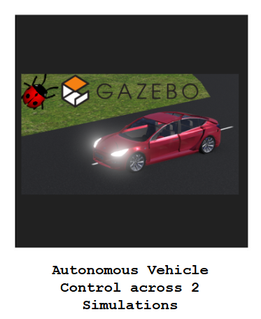
Control of an Autonomous Vehicle in 2 Different Simulation Environments
Autonomous vehicles have several diverse applications, from taxicab services to mining material transportation, and are poised to develop dramatically over the next decade due to research funding and industry support. To aid in this development, a firm understanding of how autonomous vehicles maintain heading along reference paths, navigate complex lane changing maneuvers, and possess the capability to transfer the necessary algorithms to a real-world setting is paramount. This project explores how these three areas can be developed through a Webots simulation of an autonomous Tesla sedan and, for real-world application potential, a Gazebo simulation environment built upon a ROS middleware framework popular with hardware-based implementations.
Since testing on a real autonomous vehicle would be prohibitively expensive, a simulation environment complete with GPS-esque waypoints and approximated sensor readings was created. This environment allowed for the development of a PID steering controller, which acted as a baseline against more elaborate controllers. The PID steering controller and subsequent implementations use two main metrics for measuring performance: total time to complete the track and the error between the center of the road and the center of mass of the car. Using the cross-track error as a direct way to measure the error of the car, a PID steering controller was constructed that traversed the track in 169 seconds with an average cross-track error of 0.63 meters. To improve upon the PID controller, which does not account for the model parameters of the autonomous vehicle, an LQR steering controller was devised to improve upon this performance. By adding model information and tuning certain hyperparameters, the steering controller reduced the total time around the rack by 21% with a 0.02 meter cross-track error increase.
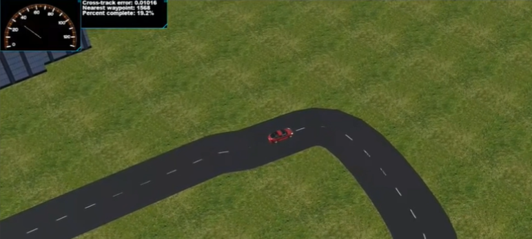 LQR controller performing a sharp (~90 degree) turn on the simulated track.
In addition to controllers that ensure proper driving, autonomous vehicles are expected to negotiate complex scenarios using planning algorithms at a similar scale to human drivers. To simulate a driving scenario requiring a planning algorithm, another opponent vehicle was added to the simulation that the controlled vehicle would have to navigate around in a lane-change maneuver using the A* path planning algorithm. The A* algorithm uses a graph search technique that finds the shortest viable path to solve the given problem. With this shortest viable path, the LQR-controlled autonomous vehicle was able to overtake the other vehicle and successfully avoid a collision.
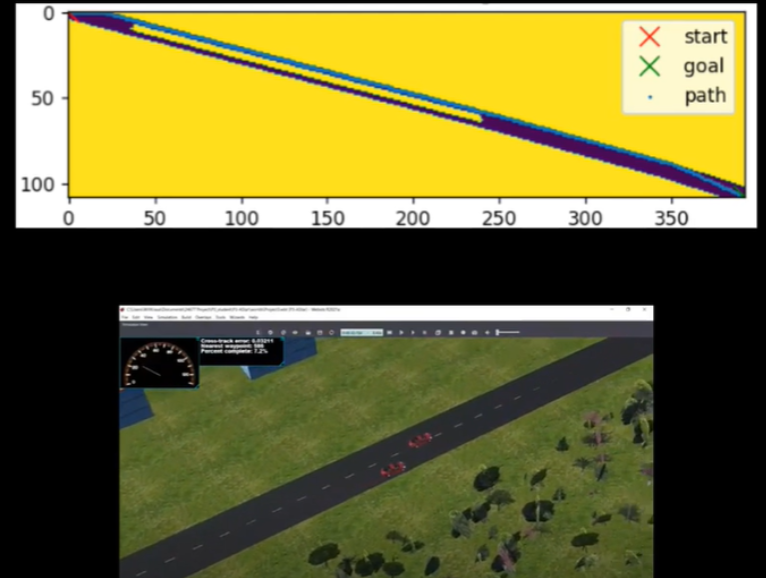 Simulated results of both the lane change in a toy scenario (top) and the actual simulation (bottom). The toy scenario draws a blue path around the yellow restricted areas that includes the future path of the adversarial vehicle.
Results Video + Controller Explanation
In conclusion, both the LQR controller and A* path planning algorithm were successfully tested in simulation and show improvement over more naive algorithms. As a future goal to build upon this work, the simulation environment and sensor readings were transferred to a ROS middleware and Gazebo simulation environment. This setup for a simulated robot allows for a hardware implementation to be developed in the future, since the open-source ROS structure has several resources for developing real-time hardware communication and control.
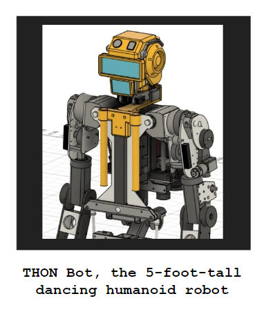
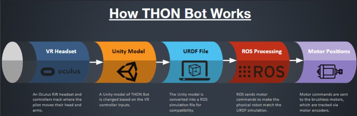
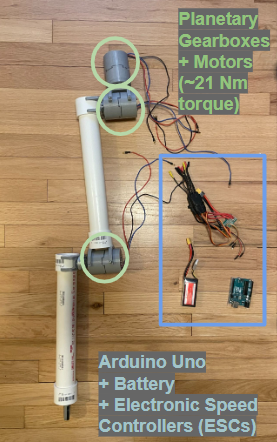
THON Bot: 5 Foot Tall Dancing Humanoid Robot
As a way to build advanced experiences for the Robotics Club, I created the THON Bot project. THON Bot is a 5 foot humanoid dancing robot that will interact with attendees for 48 hours continuously at THON 2025, which is a dance marathon that raises funds for pediatric cancer. This is one of the most complicated and rewarding robotics projects that I have experienced at Penn State University; there are electronics and controls problems that I would not have encountered as an undergraduate in Mechanical Engineering.
As the founder of the project, I divided the project into 3 teams: Hardware, Electronics, and Simulation. On the Hardware team, I oversaw a team of interdisciplinary undergraduate engineers that designed, 3D printed, and assembled plastic and metal components of THON Bot.
In the future, THON Bot has a variety of uses outside of the THON dance marathon. The project has functions and hardware that would benefit Human-Robot Interaction research or answer ethical questions about the nature of robots in society.
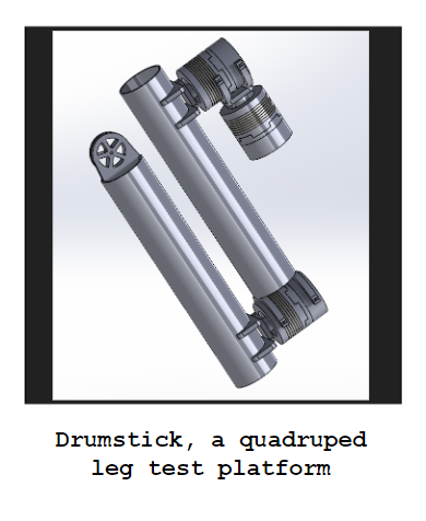
Drumstick: Testing Quadruped Leg Principles
To prepare for graduate school, I decided to construct a quadruped leg in my free time over the summer using off-the-shelf components and 3D printed parts. The design of the leg is loosely based on projects from the Open Dynamics Robot Initiative (https://open-dynamic-robot-initiative.github.io), but I replaced the pancake motors with drone motors I already had with a 100:1 gearbox for increased torque. Also, the knee linear actuator common across different quadruped designs has been replaced with a motor directly attached to the joint for ease of use.
One of the areas I am particularly interested in studying further is how to modify electromechanical designs to increase the capabilities of mobile robots. Most of the parts in the quadruped leg are replaceable and can be modified with tools common to makerspaces; this allows me to implement changes in both the control systems and the hardware design of the robot to deepen my understanding of specific concepts.
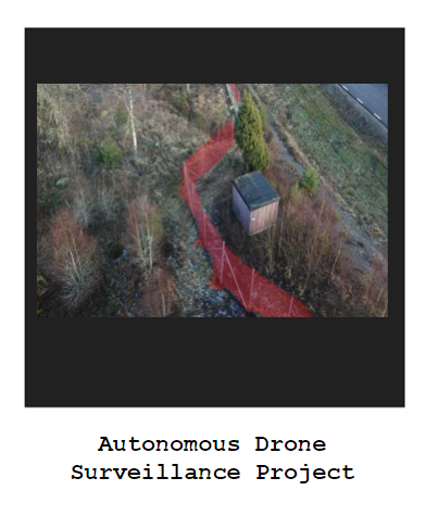
Autonomous Surveillance of Restricted Area Using Drones
AstaZero AB has an autonomous vehicle testing and research facility in a heavily wooded area in Sweden. This facility is surrounded by an approximately 10 kilometer fence to prevent moose, deer, and other animals from interrupting outdoor experiments. The team had the opportunity to automate this process using existing drone hardware at AstaZero.
A line detection software was created using Python and the openCV programming library. The code isolates the fence in the captured drone video and flags any gaps in where the fence appears.
The drone flight program is built using the DSS (Drone Security System) library and Python code. Perimeter fence GPS coordinates are recorded into the system and the drone flies to a certain altitude to detect the fence, reaches all GPS locations, and lands safely.
Overall, the project was chosen for Best Project Award out of nearly one hundred senior student teams at Penn State University. The project was tested at AstaZero’s track in Sweden successfully and executed the mission with assistance from the Chalmers University teammates.